
Introduction
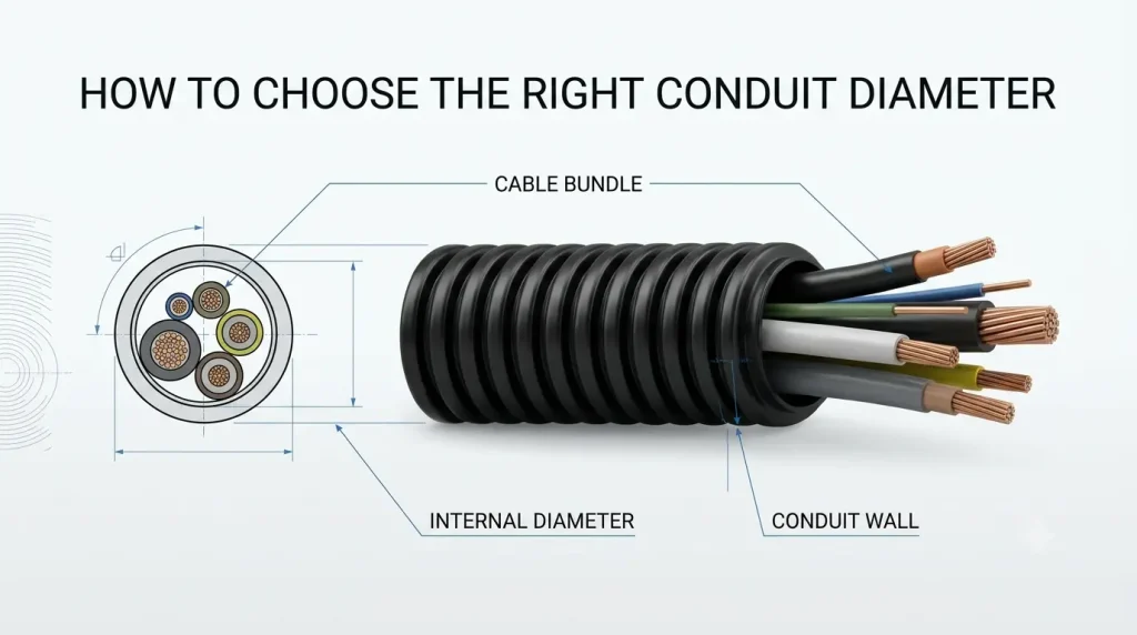
So getting the correct conduit diameter is an important part of designing a reliable cable protection system. A conduit that is too small can make cable installation very difficult, can also increase friction, restrict movement, and also create unnecessary stress on the cables. On the other hand, an excessively large conduit can increase material cost and may provide poor mechanical support for the cable bundle.
The correct size should therefore provide enough internal space for the cables while also allowing practical installation, bending, movement, heat dissipation, and where required future cable additions.
This is particularly important in industrial applications where flexible conduits are routed through control panels, automation equipment, machinery, robotic systems, electrical cabinets, moving assemblies.
The key question is not simply:
“What is the diameter of my cables?”
It is:
“How much internal space does my complete cable bundle require under actual installation conditions?”
What is Conduit Diameter?
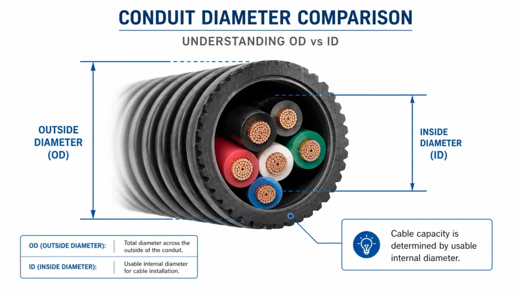
Conduit diameter refers to the diameter of the conduit, but it is important to distinguish between outside diameter (OD) and inside diameter (ID).
Outside Diameter (OD)
The outside diameter is the total diameter measured from the exterior surface of the conduit.
It is important when considering:
- Fitting compatibility
- Cable gland or connector selection
- Clamps and mounting accessories
- Available installation space
- Routing through brackets or openings
Inside Diameter (ID)
The inside diameter is the usable opening through which the cables pass.
For cable bundle selection, inside diameter is the critical measurement.
A conduit may have a relatively large outside diameter but a smaller usable internal opening because of its wall thickness or construction.
Therefore, you should not select a conduit simply by comparing the cable bundle with the conduit’s outside diameter.
Always check the manufacturer’s specified internal diameter.
Step 1: Determine the Number of Cables
Start by recognizing every cable that will pass through the conduit.
For example, an industrial machine might contain:
- 4 power cables
- 6 control cables
- 2 sensor cables
- 2 communication cables
That gives you a total of 14 cables.
However, simply counting the cables is not enough. Cables with different diameters occupy different amounts of space.
A bundle containing ten 2 mm cables is very different from a bundle containing ten 10 mm power cables.
Step 2: Measure the Cable Diameter
Measure or obtain the outside diameter of each cable from the cable manufacturer’s datasheet
For example:
Cable Quantity Outside Diameter
Power cable 3 8 mm
Control cable 4 5 mm
Sensor cable 5 3 mm
Never estimate cable diameter when accurate technical information is available.
Cable construction can vary considerably depending on:
- Conductor size
- Insulation thickness
- Number of cores
- Shielding
- Armouring
- Outer Jacket
- Voltage rating
- Cable construction standard
Using the actual cable OD will produce a much more reliable conduit-size calculation.
Step 3: Calculate the Approximate Cable Bundle Area
When several round cables are installed together, simply adding their diameters does not give the required conduit diameter.
Instead, the approximate cross-sectional area occupied by each cable can be calculated using:
Cable area = π × (d/2)²
Where:
d = outside diameter of the cable
π ≈ 3.1416
For example, a cable with an outside diameter of 8 mm has an approximate cross-sectional area of:
π × (8/2)² = 50.3 mm²
For three such cables:
50.3 × 3 = 150.9 mm²
The same calculation can then be performed for the remaining cables.
The total gives you an approximate cross-sectional area of the complete cable bundle.
However, this is only the beginning of conduit sizing.
Why Cables Fill Ratio Matters
Cables and wires are round, so when you place multiple cables inside a conduit, small empty spaces naturally exist between them.
This means you can’t treat the conduit as if its entire internal area is occupied by cable material.
For practical installations, you should allow additional space around the cable bundle.
This is commonly addressed using a cable fill ratio or conduit fill percentage.
The appropriate fill limit depends on the applicable electrical code, conduit type, installation method, number and type of conductors, and application.
For industrial flexible conduit, the manufacturer’s recommendations and the relevant installation standard should always be checked.
Why Not Fill the Conduit?
A completely packed conduit creates several problems.
It can make:
- Cable insertion more difficult
- Cable removal more difficult
- Future maintenance harder
- Cable movement more restricted
- Bending more difficult
- Friction higher
- Heat dissipation less effective
A little additional internal space can therefore make a significant difference during installation and maintenance.
A Simple Example
Suppose an industrial cable bundle consists of:
3 cables x 8 mm diameter
4 cables x 5 mm diameter
5 cables x 3 mm diameter
The approximate cable areas are:
3 × 50.3 = 150.9 mm²
4 × 19.6 = 78.4 mm²
5 × 7.1 = 35.5 mm²
Total approximate cable area:
150.9 + 78.4 + 35.5 = 264.8 mm²
The conduit therefore needs an internal cross-sectional area greater than the calculated cable area, with an appropriate allowance for cable fill, installation conditions, movement, and future requirements.
This illustrates an important point:
The conduit diameter should be selected from its usable internal diameter – not simply by adding the diameters of the individual cables.
